A review GC9310 gas chromatograph is a new type of general-purpose gas chromatograph with micro-computerization, high performance and low price. The instrument fully absorbs the advanced technology of similar products in foreign countries today. The GC9310 has the advantages of high stability and reliability, simple and reasonable structure, convenient operation and beautiful appearance.
Instrument performance and features:
1. The main control circuit of the instrument uses a micro-processing system and a large-scale integrated circuit. It adopts man-machine dialogue interface and adopts large-screen LCD Chinese character display technology, which is intuitive to display, easy to operate, easy to learn and use. All Chinese real-time display of all parameter settings and actual values, suitable for university teaching use and instrument operation of enterprise general instrument operators. Wide application range, suitable for trace detection of environmental protection, atmospheric, water and other pollution; organic chemistry; synthetic research; health quarantine; pollution detection analysis and research.
2. Stable and reliable temperature control system.
2.1 Automatic control circuit, full keyboard operation, there are five separate high-precision control systems, in which the oven temperature can achieve five-stage temperature programming. A wide range of complex sample analysis can be performed according to customer needs.
2.2 Advanced rear door opening technology ensures that the oven temperature of the instrument can have good temperature control accuracy when it is close to room temperature.
3. Stable and reliable airflow system
3.1 The carrier gas path adopts a dual stable gas path system that is stabilized first and then stabilized.
3.2 Capillary split/splitless injector, flexibility can be combined with the circuit control section for automated split/splitless injection.
3.3 The back-flow control split/splitless injector is used to give a stable pre-column pressure and improve the stability of the capillary system. Dedicated to capillary analysis.
3.4 Capillary injector with diaphragm cleaning function, effectively prevent the peak phenomenon of the injector at high temperatures.
3.5 flow control valve with digital knob adjustment, intuitive, and good reliability.
3.6 The pressure before the column is displayed on the pressure gauge.
4 There are two choices of injectors
4.1 Packed Column Sampler for analysis with packed columns and large diameter capillary columns.
4.2 Capillary injector is suitable for the analysis of small diameter, large diameter capillary columns.
5 choices of detectors
5.1 It can install dual hydrogen flame detector and single and double amplifier signal output, and install TCD thermal conductivity detector.
5.2 can be equipped with a single thermal detector and a single hydrogen flame detector.
Second instrument technical indicators and use requirements
1. Standard oven temperature index:
Oven temperature range: 15 ° C ~ 399 ° C (increment 1 ° C) at room temperature
Temperature control accuracy of the oven: better than ±0.1 °C (measured at 200 °C)
The oven temperature is programmed: the five-step lift rate setting: 0.1 °C ~ 40 °C / min (increment 1 °C), 200 °C measured all steps constant temperature: 0 ~ 655min (increment 1min)
2. Thermal Conductivity Detector (TCD)
1) Sensitivity: S≥3000mv.ml/mg
2) Baseline noise: ≤20μv
3) Baseline drift: ≤50μv/30min
4) Carrier gas flow rate stability: ≤ 1%.
3. Flame ionization detector (FID)
1) Detection limit: ≤8×10-12g/s
2) Baseline noise: 5×10-14A
3) Baseline drift: ≤ 2 × 10-13A / 30min
4. Injector, detector, thermal cell temperature index 1) Temperature range: 15 ° C ~ 399 ° C (increment 1 ° C) at room temperature
2) Temperature control accuracy: better than ± 0.1 ° C (200 ° C measured)
5. The instrument requires power supply voltage: 220V ~ ± 22V 50Hz ± 0.5Hz
Rated power: <1800W
Ambient temperature: +5 ° C ~ +35 ° C
Relative humidity: ≤85%
The instrument shall be placed in a place where there is no corrosive gas or an electric field or magnetic field that affects normal operation. The instrumentation workbench shall be stable and shall not be vibrated. There must be no electric furnace and fire within 2m from the hydrogen bottle.
1.2 Instrument completeness and optional accessories
1.2.1 Complete set GC9310 gas chromatograph basic type includes chassis, double packed column sampler, full packed column, carrier gas and auxiliary gas path, microcomputer temperature controller, flame ionization detector and micro current amplifier, two Stainless steel packed column with 0.6m length and 2mm inner diameter (7% SE-30chromosorbGHB or 5% OV-101, 100 mesh to 120 mesh).
a) GC9310 gas chromatograph base type
b) Accessories spare parts (see accessories spare parts list)
1.2.2 Optional Accessories The GC9310 gas chromatograph has the following accessories for users to choose. If you need to order, you can make a note when you order the basic type, or you can choose it at any time during the use of the instrument.
a) GC9310-TCD thermal conductivity cell detector; GC9310 - high sensitivity TCD
b) Six-way plane switching valve gas injector (manual, automatic control)
c) Reformer (including nickel methanation converter)
d) Capillary split/splitless injector
e) Multiple types of chromatography workstations
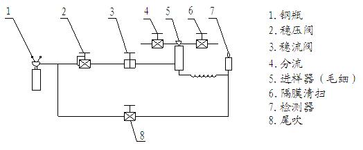
1.3 How the instrument works The gas chromatograph uses a gas as the mobile phase (carrier gas). When the sample is "injected" into the injector by a microsyringe, it is carried by the carrier gas into a packed column or capillary chromatograph. Due to the difference in the distribution or adsorption coefficient between the mobile phase (gas phase) and the stationary phase (liquid phase or solid phase) of each component in the sample, the components are repeated between the two phases under the flushing of the carrier gas. The sub-distribution allows the tissues to be separated in the column, so that the components are separated in the column, and then the components connected to the column are sequentially detected according to the physicochemical properties of the components. The GC9310 gas chromatograph is an analytical instrument manufactured according to the above principle. GC9310 gas chromatograph block diagram, see Figure 1-1

Figure 1-1 Block diagram of GC9310 gas chromatograph
1.4 Mainframe structure of the instrument The GC9310 gas chromatograph consists of flow control components, injectors, column ovens, detectors, temperature and detector circuit components, and chromatographic workstations.
The middle part of the basic instrument is the column box, the upper part is the microcomputer temperature controller, the lower part is the FID micro current amplifier, the left part of the instrument is the flow control part and the gas path panel, and the right part of the upper part of the oven is the ionization detector installation. The position (two flame ionization detectors installed in the base) and the thermal conductivity detector (TCD) are installed. The left side of the oven is a double packed column injector or capillary injector.
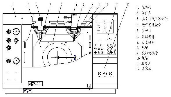
Host structure diagram 1 (main view)
Host structure diagram 2 (left view)

Host structure diagram three (right view)
1.5 Chromatograph oven GC9310 GC cartridge has a large volume, can be installed with double packed column or capillary column, and has a fast temperature rise and fall. This machine adopts a noise reduction motor, which has a smooth running machine and is equipped with an automatic rear door opening device.
When the oven needs to be cooled, the cooling air inlet and the hot air exhaust port at the rear of the box are automatically opened, and the cooling air enters the oven from the air inlet, and the hot air in the oven is replaced from the hot air exhaust port, so that The oven is cooled quickly.
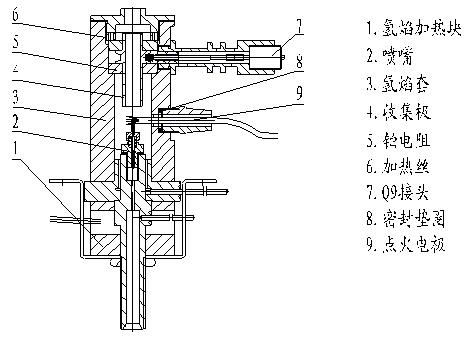
1.6 Injector The instrument base is equipped with a dual packed column injector. Users can flexibly install as a capillary split/splitless injector as needed. The structure of the injector is shown in the figure. The double-filled column sampler is installed in the heat-conducting body on the left side of the top of the main body, and the electric heating element and the ceramic platinum resistance are simultaneously installed in the heat-conducting body, and the temperature is controlled by the microcomputer temperature controller.
The packed column injector in the figure is an example of a Ñ„3mm stainless steel column (column injection). The inner diameter of the instrument is Ñ„3.2mm column joint, which is suitable for column tube with outer diameter Ñ„3. In addition, the packed column injector can also be installed with Ñ„6mm stainless steel column and Ñ„5.7mm glass column, and the capillary injector can be installed with Ñ„0.32mm and Ñ„0.53mm quartz capillary column.
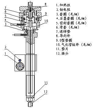
1-6 Figure (1) Capillary injector structure diagram
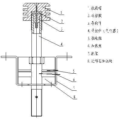
1-6 (2) filled pool injector
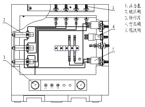
1.7 Pneumatic Control System The gas flow path of the GC9310 gas chromatograph is a double packed column flow path structure, and a separate capillary split flow regulating valve. A capillary analysis flow path can be installed as needed, and two different carrier gas flow paths can be installed at the same time. The hydrogen and air flow paths are dual flow paths, and each channel can be independently adjusted.
1.7.1 Carrier gas flow The carrier gas flow is regulated by the steady flow valve. The carrier gas steady flow valve is mechanically scaled. The upper pressure regulator provides a stable input pressure. The output flow of the steady flow valve can be checked from the corresponding flow curve. (Note: the flow is related to the type of gas), that is, each scale on the steady flow valve knob has a standard curve relationship with the flow rate represented. The scale-flow curve is the same for the three steady flow valves on the instrument (filled column A, B, and C capillary flow paths). More accurate flow values ​​can be measured with a soap flow meter).

1-7 (1)
1-7 (2)
1.7.2 Hydrogen and Air Flow The auxiliary gas path of the GC9310 Gas Chromatograph has air and hydrogen. Installed on the upper left side of the instrument. Hydrogen and air flow adjustment adopts scale needle valve. Hydrogen and air needle valve provides stable input pressure by upper pressure regulator. The output flow of hydrogen and air needle valve can be checked from the corresponding scale-flow curve table. Got it. In other words: to set and change the hydrogen and air flow, just change the scale indication of the corresponding needle valve knob. The air and hydrogen adjustment knobs and panels are on the top left of the main unit (you must flip the cover on the panel when in use).
Advice Please do not change the output pressure of the internal pressure regulating valve of the gas path. That is, the three shafts at the rear of the pneumatic system should not be adjusted to avoid affecting the validity of the scale-flow curve and the output accuracy.
2. Microcomputer Temperature Controller The GC9310 gas chromatograph's microcomputer temperature controller provides a wide temperature range and high precision for a total of five controlled objects in the column box, injector, detector and thermal conductivity cell, capillary injector. Temperature control. The oven can achieve five-stage temperature programming. Because the control system adopts advanced software and hardware technology, the performance is reliable and stable, the anti-interference is good and the temperature overshoot is small. In addition to temperature control and Chengsheng, it also has temperature limit setting, analysis time counting, temperature maintenance, dynamic scanning of actual temperature, automatic opening of the rear door of the oven when cooling, power protection data protection, the instrument has self-test function, such as error, it Functions such as the temperature controller are automatically turned off. In addition, a variety of chromatographic workstation connections are available. The controller can also realize the microcomputerization of the range and polarity selection of the FID amplifier and the setting and display of the TCD current.
two. 1 panel and keyboard settings:
2.1 Boot, screen display: model, temperature settings, factory name, phone.
2.2 Press Main Menu Display: Temperature Program Temperature Capillary Injection Detection 1
Detection 2
External event
When the cursor displays the temperature, press the number keys to set each temperature, press the input key after the setting value, and then press the operation to set the temperature.
2.3 Temperature programming Set the instrument to warm up, press the main menu, then press the â–¼ corner down key to warm up the program, then press the enter key to enter the temperature programming display interface, set the temperature from the initial temperature, press the input key to the initial hold time setting. Set the value, press the enter key to enter the first order, enter the first-order rate cursor, press the number key, then press the enter key to enter the first-order temperature, press the number keys to set the desired temperature. Press the enter key to enter the first-order hold time, press the number key, set the desired time and press the enter key, so that the first-order program temperature is set. Press the start button again to run the first-order programming. If you need to set several steps of program temperature, set the following steps to program temperature according to the first-order temperature programming method.
2.4 Capillary Injection Setup The capillary injector split/splitless setting. Press the main menu to enter the capillary injection, press the enter key and the screen displays the temperature.
Initial state No shunt switching time 0.01 to several hours to do this project requires additional customization
2.5 Setting Temperature of Hydrogen Flame Detector Press the â–¼ key to display the range cursor, press 7-10 digits, and press the enter key. This way the amplifier range is set.
Press the â–¼ key to the ignition cursor input cursor to ignite, press the input key to perform ignition, press the down â–¼ to switch the signal positive and negative polarity, press the number key 1 input key, the screen display polarity is positive. Press the number key 0, press the enter key, the screen display polarity is negative
Hydrogen flame detector
2.6 Detecting the two thermal conductivity detector settings Press the main menu to the detector 2, press the input, the screen displays the thermal conductivity detector. Press the â–¼ key to the current cursor, press the number key 0-220, and then press the enter key. This current is set.
Polarity setting: Digital health 1 is positive 0 is negative, and the thermal conductivity setting is completed according to the input key.
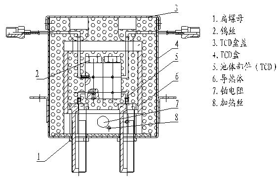
Thermal conductivity cell structure
2.7 Setting and Operation of External Events Cursor Displaying External Events 1 Press the Enter key to display:
Set value Initial state Off Switching time 0.00
Switching time 0.00
Switching time 0.00
Switching time 0.00
The initial state is turned on and off with 0 and 1 settings.
The function of the external event is mainly the automatic switching and time control of the electromagnetic four-way, six-way, eight-way and ten-way valves, which is more convenient for the user to analyze the sample.
To do this function requires the user to order separately.
III. The steps of GC9310-TCD constant temperature analysis are as follows:
1) Install the TCD detector and TCD constant current power supply unit.
2) Connect the external air path of the carrier gas (H2) and check for leaks
3) Install two aged columns (from packed column injector to TCD detector)
4) Connect the power cord of the chromatography workstation.
5) Connect the signal line of the chromatographic workstation.
6) Open the carrier gas source and rotate the low pressure rod until the hydrogen low pressure meter indicates 0.1 MPa to adjust the two carrier gas steady flow valves on the carrier gas adjustment panel on the left side of the main unit, and the A and B two-way carrier gas flow regulation. The required value (the number of fulcrum knobs can be found by the “flow parameter tableâ€. Please note: the “flow parameter table†for the carrier gas is to be found at this time)
7) Turn on the main power supply and set the oven TCD detector and injector temperature respectively and start the temperature control.
8) Adjust the “Zero†knob of the TCD steady current power supply to recall the recorded chromatographic baseline until the baseline is stable.
9) When the TCG detector is working, it is necessary to observe the rule of “first carrier gas (H2), post-rise temperature, and current additionâ€: that is, when the TCD detector does not pass the carrier gas (H2), the bridge current must not be set. Otherwise, it will damage the tungsten wire and even burn it.
IV. GC9310FID operation steps:
1. Connect N2 gas
2. Install the column in the oven (filled column or capillary column)
3. Turn on N2 to adjust the flow
4. Start setting temperature FID, oven, temperature required for injection
5. When the temperature is constant, turn on the air, hydrogen, set the required flow, and then ignite
6. Perform the injection analysis and data logging after adjusting the required range of the amplifier and adjusting the chromatographic workstation until the baseline is stable.
7. When shutting down, turn off the hydrogen and air first, then turn off the N2 gas after the standby unit cools down.
V. Maintenance and troubleshooting of the instrument
5.1 Maintenance of the instrument The correct maintenance of the instrument not only enables normal operation, but also prolongs the life of the instrument. The following points must be observed when maintaining the instrument:
a) The instrument should be operated strictly under the specified conditions and the power supply is well grounded.
b) Work strictly in accordance with the operating procedures. It is strictly forbidden to enter oil, organic substances and other substances into the detector and pipeline to avoid blockage of pipes or deterioration of instrument performance.
c) It is forbidden to exceed the allowable temperature of the fixed liquid in the stationary phase. The general column temperature is lower than the allowable temperature of the fixed liquid. The column temperature should be lower when performing high sensitive operation.
d) The external air source input to the GC9310 pressure must be 343000Pa (equivalent to 3.5kg/cm2 ~ 5kg/cm2), the air input pressure to 294000Pa ~ 588000Pa (equivalent to 3kg / cm2 ~ 6kg / cm2), hydrogen input to the pressure 196000Pa to 343000Pa (equivalent to 2kg/cm2 to 3.5kg/cm2). If hydrogen is used as the carrier gas, the pressure input to the carrier gas inlet should be
343000Pa (equivalent to 3.5kgf/cm2).
5.2 Common chromatographic output signal judgment and troubleshooting methods, see table
| malfunction | Fault judgment | Inspection method and repair |
| No peak | (1) Amplifier power supply disconnected (2) Ion wire break (3) No carrier air flow (4) Micro syringe clogging (5) Sampler silicone rubber leak (6) Column connection loose (7) No fire (FID ) (8) FID polarization voltage is not connected or bad contact | (1) Check the amplifier, fuse (2) Check the ion line (3) Check the carrier flow path, block it, or run out of gas in the cylinder (4) Replace the syringe (5) Replace the silicone rubber (6) Tighten the guide column (7) Ignition (8) is connected to the polarization voltage, or the polarization voltage connection is eliminated. |
| 2. Normal residence time and reduced sensitivity | (1) The detector has no high voltage (FID) | (1) Check or install high voltage |
| 3. Trailing peak | (1) The injection temperature is too low (2) The sample tube is contaminated (sample or silicone rubber residue) (3) The temperature of the column is too low (4) The injection technique is too low (5) The column is not properly selected (the sample reacts with the column carrier or the fixative) | (1) Re-adjust the temperature of the injector (2) Clean the injector tube with solvent (3) Increase the temperature of the column (4) Improve the injection technique, and make the needle faster (5) Re-select the appropriate chromatogram column |
| 4. Extend the tongue | (1) The column exceeds the load, the sample amount is too large (2) the sample is agglomerated in the system | (1) Reduce the sample volume (2) first increase the column temperature, then select the appropriate injector, column, detector temperature |
| 5. No separation peak | (1) The column temperature is too high (2) The column is too short (3) The fixing solution is lost (4) The fixing solution or the carrier is not selected correctly (5) The carrier gas flow rate is too high | (1) Reduce the column temperature (2) Select a longer column (3) Replace the column or aging column (4) Select the appropriate column (5) Reduce the carrier gas flow rate |
| 6. Pingding Peak | (1) Amplifier input saturation | (1) Reduce sample size and reduce amplifier sensitivity |
| 7. Anti-peak | (1) The sample enters the other one. (2) The positive and negative switch positions are misplaced. | (1) The sample enters the appropriate column (2) Correct the positive and negative switch in the correct position |
| 8. Irregular baseline fluctuations during constant temperature operation | (1) Instrument grounding is not good (2) Column fixed fluid loss (3) Carrier gas leakage (4) Detector contamination (5) Improper carrier gas flow selection (6) Hydrogen, improper air selection (FID) (7) The amplifier itself is unstable | (1) The instrument should be well grounded (2) The fixed liquid should be properly selected, the column should be fully aged, and the temperature of the column should not be raised to the limit of the fixed liquid (especially the high sensitivity detector) (3) Leak detection (4) Cleaning detector (5) Adjust the carrier gas steady flow valve to adjust the carrier gas flow rate properly, and ensure the total pressure of the carrier gas cylinder is between 50kg/cm2 and 150kg/cm2. (6) Proper adjustment of hydrogen and air flow (7) Check amplifier, repair amplifier |
| 9. Recording suddenly returns to below baseline and extinguishes fire (FID) | (1) The sample volume is too large (2) The hydrogen or air flow rate is too low (3) The carrier gas flow rate is too high (4) The flame nozzle is contaminated (or blocked) (5) Run out of hydrogen | (1) Reduce the sample volume (2) Re-adjust the hydrogen and air flow rate (3) Select the appropriate carrier gas flow rate (4) Clean the flame nozzle (or pass the flame nozzle) (5) Ensure that the hydrogen source has sufficient hydrogen |
| 10. Baseline does not return to zero | (1) Due to excessive loss of column (FID) (2) Detector contamination | (1) Clean the detector with a column that has less loss (2) |
| 11. There are certain short burrs in equal intervals | (1) Water condenses in the hydrogen line (water generally comes from a hydrogen source) (2) Air leakage (3) There is a blockage in the flow path. | (1) Eliminate water from the pipeline and exchange or activate the desiccant in the hydrogen filter (2) Leakage (3) Remove impurities in the flow path. If there is impurity in the column, the column temperature can be appropriately increased (4) Adjust the proper hydrogen and air flow |
| 12. Baseline noise is large | (1) column contamination or column loss is too large (2) carrier gas pollution (3) carrier gas flow rate is too high (4) carrier gas leakage (5) poor grounding (6) oxygen inlet pollution (7) hydrogen flow rate too High or too low (FID) (8) Air flow rate is too high or too low (FID) | (1) Replace the column (2) Replace or regenerate the carrier gas filter (3) Re-adjust the carrier gas flow rate (4) Detect the leak (5) Ensure the instrument is well grounded (6) Clean the sample tube in the injector and remove the silicon Rubber residue (7) readjust the hydrogen flow rate (8) readjust the air flow rate |
| Â | (1) Air or hydrogen pollution (2) Water condensation in FID (3) Poor contact of detector cable (4) Insulation of detector is small (ionization detector) (5) Detector electrode or spout and bottom contamination | (1) Replace hydrogen and air filter (2) Increase FID temperature to remove moisture (3) Replace or repair cable (4) Clean detector insulator wash detector |
Orthopaedic External Fixator,Orthopaedic External Fixation,Near Joint External Fixators ,Orthopedic External Fixation
Jiangsu Health Medical Technology Development Co., Ltd. , https://www.medicalhos.com